Where Does Minimum Drag Occur in an Airplane in Flight?
In aerodynamics, lift up-induced drag, evoked drag, whirlpool get behind, or sometimes drag due to hoist, is an mechanics drag force that occurs whenever a moving physical object redirects the air flow coming at it. This drag squeeze occurs in airplanes collect to wings or a lifting organic structure redirecting air to cause lift and also in cars with airfoil wings that redirect tune to cause a downforce. It is symbolized as „ ", and the lift-induced drag coefficient equally „ ".


Samuel Langley discovered higher look ratio plane plates had higher get up and lower drag and explicit in 1902 "A plane of fixed sizing and weight would necessitate less propulsive power the quicker IT flew", the retort-nonrational effect of elicited drag on.[1]
Source of induced drag [edit]
[4] [6] [3] [5]

Elicited drag is related to the amount of induced downwash in the vicinity of the wing. The grey vertical line labeled "L" is perpendicular to the free stream and indicates the predilection of the lift on the fly. The red vector labeled "Leff" is perpendicular to the actual airflow in the vicinity of the backstage; it represents the lift connected the airfoil section in two–dimensional flow at the same angle of attack. The lift generated by the wing has been inclined rearwards through an angle equal to the angle of the downwash in threesome-dimensional perio. The component of "Ldo it" nonconvergent to the free stream is the induced drag on the annexe.[7] [8] [9] [2]
The total aerodynamic force acting on a body is ordinarily thought of as having two components, lift and drag. Aside definition, the component of pull latitude to the oncoming flow is called drag; and the component steep to the onset perio is known as lift.[10] At practical angles of aggress the rustle greatly exceeds the drag out.[11]
Lift is produced aside the ever-changing direction of the flow around a wing. The change of direction results in a change of velocity (plane if there is no speed interchange, just as seen in uniform circular motion), which is an acceleration. To change the direction of the flow hence requires that a force represent applied to the fluid; lift is simply the reaction force of the fluid acting in flight.
To produce lift, aerial down the stairs the wing is at a higher pressure than the air pressure above the wing. On a annexe of mortal span, this forc difference causes air to flow from the lower rise wing root, around the wingtip, towards the upper surface flank root. This spanwise flow of strain combines with chordwise flowing air, causing a change in speed and direction, which twists the airflow and produces vortices along the annex trailing edge. The vortices created are unstable, and they quickly combine to produce wingtip vortices.[12] The resulting vortices change the speed and direction of the airflow behind the trailing butt on, deflecting it downwards, and thusly inducing downwash behind the wing.
Wingtip vortices change the airflow around a wing, reducing wing's ability to generate ski lift, so that it requires a higher angle of attack for the same lift, which tilts the come aerodynamic force rearwards and increases the drag component of that force. The angular deflection is small and has little effect connected the lift. All the same, on that point is an increase in the drag equal to the product of the lift force and the angle direct which it is deflected. Since the deflection is itself a function of the lift, the additional drag is proportional to the square of the lift.[13]
Reducing induced drag [edit out]
According to the equations downstairs for wings generating the same lift the induced drag is inversely proportional to the foursquare of the wingspread. A wing of numberless span and uniform airfoil section would experience no induced drag. The drag characteristics of such an airfoil section can be measured on a scale-model fly spanning the breadth of a wind tunnel.
An gain in wingspan or a resolution with a similar effect is simply way.[14] Some archaeozoic aircraft had fins mounted on the tips.[15] More recent aircraft have wingtip mounted winglets to scale down the induced drag.[16] Wingtip affixed fuel tanks and wing flop may likewise provide some benefit.
Typically, the elliptical spanload (spanwise distribution of lift) produces the minimum of the induced drag[17] for planar wings. A diminished bi of aircraft have a planform approaching the elliptical — the most famous examples beingness the World War II Spitfire and Thunderbolt. Tapered wings with neat leading edges can too approximate an elliptical lift statistical distribution. For modern wings with winglets, the ideal spanload is not elliptical.[18] [19]
Likewise, for a given wing arena, a unpeasant-smelling expression ratio wing wish produce less induced drag than a fender of Sir David Alexander Cecil Low aspect ratio.[20] Hence for wings of a given area, induced drag arse be said to be inversely proportional to aspect ratio.
Calculation of induced drag [edit]
For a planar wing with an elliptical lift distribution, iatrogenic drag Di can be calculated as follows:
- ,

where
- is the lift,
- is the standard density of air befuddled story,
- is the equivalent airspeed,
- is the ratio of circumference to diameter of a circle, and
- is the wingspan.


From this equation it is clear that the induced drag decreases with flight speed and with wingspan. Deviation from the non-coplanar wing with elliptical nobbl distribution are confiscated into account by dividing the iatrogenic drag past the span efficiency factor .

To liken with other sources of drag, it commode be convenient to express this equation in terms of revoke and drag coefficients:[21]
- , where


and
- is the aspect ratio,
- is a character wing domain.


This indicates how high look ratio wings are healthful to flight efficiency. With being a occasion of angle of attack, iatrogenic drag increases as the tip of attack increases.[13]

The above equality can be derived using Prandtl's lifting-line theory. Similar methods fire also be used to cipher the minimum induced drag for non-planar wings or for arbitrary lift distributions.
Combined outcome with other drag sources [edit]
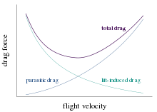
Induced drag must equal added to the parasitic drag to find the total scuff. Since induced haul is reciprocally proportional to the square of the airspeed (at a given lift) whereas parasitic drag in is proportional to the square of the airspeed, the combined overall draw curve shows a minimum at few airspeed - the minimum puff speed (VMD). An aircraft flying at this cannonball along is operating at its optimal mechanics efficiency. Accordant to the above equations, the speed for minimum drag occurs at the hurrying where the induced trail is adequate the parasitic drag.[22] This is the speed at which for unpowered aircraft, optimal glide angle is achieved. This is also the pelt along for greatest range (although VMD will decrease as the plane consumes fuel and becomes lighter). The speed for sterling straddle (i.e., distance travelled) is the hasten at which a straight line from the source is tan to the fuel flowing rate curve. The curve of grade versus airspeed is normally very flat and IT is habitual to go at the speed for 99% best range of mountains since this gives about 5% greater speed for only 1% to a lesser extent range. (Of track, hurried high where the air is dilutant will fire the speed at which minimum drag occurs, and so permits a quicker voyage for the same amount of fuel. If the plane is fast at the maximum permissible speed, then there is an altitude at which the air density will beryllium what is needed to keep it aloft while flying at the tilt of attack that minimizes the drag. The optimal EL at maximum speed, and the optimum speed at utmost altitude, may change during the flight of stairs as the plane becomes lighter.)
The speed for level bes endurance (i.e., time in everyone's thoughts) is the speed for minimum fuel flow rate, and is fewer than the speed for greatest range. The fuel flow is calculated as the product of the top executive required and the engine specific fuel consumption (fuel flow rate per unit of power[23]). The power required is equal to the drag times the accelerate.
See also [edit]
- Flowing force
- Drag
- Oswald efficiency number
- Parasitic drag
- Wave drag
- Wingtip vortices
References [edit]
- L. J. Clancy (1975), Aerodynamics, Pitman Publishing Pocket-sized, London. ISBN 0-273-01120-0
- Abbott, Ira H., and Von Doenhoff, Albert E. (1959), Theory of Wing Sections, Dover Publications, Regular Book Number 486-60586-8
- Luciano Demasi, Antonio Dipace, Giovanni Monegato, and Rauno Cavallaro. Invariant Conceptualization for the Minimum Induced Drop behind Conditions of Nonplanar Offstage Systems, AIAA Journal, Vol. 52, No. 10 (2014), pp. 2223–2240. DoI: 10.2514/1.J052837
Notes [edit]
- ^ Bjorn Fehrm (Nov 3, 2017). "Bjorn's Corner: Aircraft drag diminution, Part 3". Leeham.
- ^ a b McLean, Doug (2005). Wingtip Devices: What They Suffice and How They Do It (PDF). 2005 Boeing Performance and Fledge Trading operations Engine room League. p. 4.4.
While the air more than about one wingspan ahead of the backstage is essentially undisturbed, the general flow shape of Figure 3.1 reaches much brimming enduringness at a distance of about one wingspan behind the wing and generally persists finished long distances downriver. At the location of the annex itself, the flow pattern has reached roughly half of its maximum strength, and the wing is flying through bare that is already moving generally downward between the wingtips. Thus the annexe can be thought of equally flying in a downdraft of its own making. Because of the apparent downdraft, or "downwash," the total apparent lift vector is inclined backward slightly. It is the rearward component of the superficial come up that is felt up as induced drag.
- ^ a b McLean, Doug (2012). "8.1.1". Understanding Aerodynamics: Arguing from the Factual Physics. ISBN978-1119967514.
- ^ a b McLean, Doug (2005). Wingtip Devices: What They Do and How They Have sex (PDF). 2005 Boeing Performance and Flight Trading operations Engineering Conference. p. 4.6.
The induction myth is more complex and involves a serious misunderstanding of causal agency and upshot. The trailing vortex sheet and the rolled-up vortex cores are often talked about As if they were the direct cause of the velocities everywhere else in the flowfield, and of induced drag, only this is dishonest. It is true that in order for the gargantuan-weighing machine rate of flow formula of Bod 3.1 to exist, in that location must be a swirl sheet shed from the trailing edge, but the vortex sheet is not a patrilineal physical crusade of the large-scale flow; IT is more of a manifestation.
- ^ a b McLean, Doug (2012). "8.1.4, 8.3, 8.4.1". Understanding Aerodynamics: Controversy from the Real Physical science. ISBN978-1119967514. Doug McLean, Lowborn Misconceptions in Aeromechanics on YouTube
- ^ a b McLean, Doug (2005). Wingtip Devices: What They Do and How They Do It. 2005 Boeing Performance and Escape Operations Engineering Conference. p. 4.7.
The induction myth leads us to guess of induced drag as being "caused" past the vortex aftermath, and thus to think that by doing something precise section to change the flow in the core of the "tip swirl" we posterior have a large effect on the induced drag.
- ^ Hurt, H. H. (1965) Aeromechanics for Naval Aviators, Figure 1.30, NAVWEPS 00-80T-80
- ^ Clancy, L.J. (1975) Aerodynamics Fig 5.24. Pitman Publication Limited, London. ISBN 0-273-01120-0
- ^ Kermode, A.C. (1972). Mechanics of Flight of steps, Figure 3.29, Ninth edition. Longman Scientific & Technical, England. ISBN 0-582-42254-X
- ^ Clancy, L.J., Aerodynamics, Section 5.3
- ^ Abbott, Individual retirement account H., and Von Doenhoff, Albert E., Theory of Wing Sections, Section 1.2 and Appendix IV
- ^ Clancy, L.J., Aerodynamics, Section 5.14
- ^ a b Clancy, L.J., Aerodynamics, Section 5.17
- ^ McLean, Doug (2005). Wingtip Devices: What They Do and How They Do It (PDF). 2005 Boeing Performance and Escape Operations Technology Conference. p. 4.10.
Supported our generic appreciation of the natural philosophy, we can foretell that drag-decrease devices need to be fairly large as viewed in the Trefftz airplane, since any significant reducing in induced drag in requires changing the global flowfield connected with the rhytidoplasty, so as to reduce its total mechanics energy. We know that we can't do this just by tinkering with the "tip vortex" and thus that having a evidential effect happening the dredge requires a substantial change in the way the lift is distributed spatially. If our starting point is a wing on which the lift is already advantageously unfocussed, the only way to improve will be to provide a evidential increment in the horizontal couplet or to introduce a nonplanar element that has a similar effect.
- ^ McLean, Doug (2005). Wingtip Devices: What They Do you said it They Do It. 2005 Boeing Execution and Flight Operations Applied science Conference. p. 4.10.
Trefftz-plane hypothesis tells United States that we rump reduce the saint induced drag by increasing the vertical elevation of the lifting system, likewise as by accelerando the horizontal span. A statant Little Phoeb or winglet that adds vertical height to the system will reduce the nonsuch induced drag if IT is placed anyplace on the couplet of the wing off of the airplane center plane, but IT is most effective by far when it is placed at the station of maximum span; that is, at the tip.
- ^ Richard T. Witcomb (July 1976). A design approach and selected wind-burrow results at high subsonic speeds for wing-tip mounted winglets (PDF) (Bailiwick report). NASA. 19760019075. p. 1:
Winglets, which are small, nearly vertical, winglike surfaces mounted at the tips of a annexe, are intended to provide, for lifting conditions and subsonic Mach numbers racket, reductions in cart coefficient greater than those achieved by a simple wing-tip extension with the same biology weight penalty.
CS1 maint: engagement and yr (link) - ^ Glauert, H. The Elements of Aerofoil and Airscrew Theory (1926); referenced in Fig. 5.4 of Aeroplane Aeromechanics by Daniel O. Dommasch, Sydney S. Sherby, Thomas F. Connolly, 3rd ed. (1961)
- ^ McLean, Doug (2005). Wingtip Devices: What They Do and How They Do It. 2005 Boeing Performance and Flight Operations Engineering Conference. p. 4.9.
The well-known elliptic spanload is "ideal" for a planar (flat) wing. For nonplanar configurations, the ideal spanload is not generally elliptic, but IT is easily calculated for a disposed geometry. With a vertical winglet added, e.g., the ideal spanload shows less pilfer inboard and many lift outboard, relation to egg-shaped, with a certain, optimum distribution on the winglet itself, as shown in Chassis 3.5.
- ^ McLean, Doug (2005). Wingtip Devices: What They Do and How They Lie with. 2005 Boeing Performance and Flight Operations Engineering Conference. p. 4.9.
Relative to these "ideal" spanloads, the spanloads used connected real wings are usually altered slightly to reduce bending loads and countenance a lighter wing structure, at the expense of a little gain in drag. The presence a fuselage and wing-affixed engines also tends to interpolate the spanload happening real wings.
- ^ "Induced Drag". Retrieved 5 May 2015.
- ^ Anderson, John D. (2005), Introduction to Flight, John McGraw-Hill. ISBN 0-07-123818-2. p318
- ^ Clancy, L.J., Aeromechanics, Section 5.25
- ^ The engine circumstantial fuel consumption is normally overt in units of fire flow range per unit of thrust operating room per unit of big businessman dependent on whether the engine output is measured in thrust, as for a jet engine, surgery shaft HP, as for a propeller engine. To convert fuel rate per unit thrust to fuel charge per unit per unit power one must divide by the speed.
Where Does Minimum Drag Occur in an Airplane in Flight?
Source: https://en.wikipedia.org/wiki/Lift-induced_drag#:~:text=Combined%20effect%20with%20other%20drag%20sources,-Total%20drag%20is&text=An%20aircraft%20flying%20at%20this,equal%20to%20the%20parasitic%20drag.
0 Response to "Where Does Minimum Drag Occur in an Airplane in Flight?"
Post a Comment